
Network Bandwidth for Factories: Sizing & Monitoring Guide

Network bandwidth in a factory is the maximum data-carrying capacity of your plant network, measured in bits per second (bps, Mbps, or Gbps), and it determines whether your PLCs, machine vision cameras, historians, and office systems can all move data without starving each other. The first step is not to guess at a number — it is to measure today's peak and burst loads before you touch a single switch configuration.
Here is what to do right now:
- Measure peak bursts, not averages. Run a flow collector or SNMP poller at every IDF uplink and your WAN edge for at least two weeks to capture 95th-percentile utilization and burst events.
- Segment and protect control traffic. Place PLCs and safety systems on dedicated VLANs with QoS marking before you do anything else. A misconfigured switch can delay a control packet by milliseconds — enough to trigger a fault.
- Plan uplink upgrades based on measured data. Consumer rules of thumb (100 Mbps download for "most activities") do not apply here. Factory uplink sizing must come from your own measurements.
Pro Tip: Vision traffic is bursty by nature. A single high-resolution camera can spike from near-zero to several hundred Mbps in a fraction of a second during an inspection cycle. Average utilization will look fine right up until the uplink saturates and a control packet is dropped. Always capture burst duration and peak rate, not just the mean.
Table of Contents
- What does network bandwidth mean for a factory?
- Why does bandwidth directly affect manufacturing operations?
- How do industrial traffic classes and latency targets guide your QoS design?
- How do you measure and monitor bandwidth on the factory floor?
- How do you plan and size bandwidth for a factory network?
- How do you increase effective bandwidth without just buying bigger pipes?
- Worked bandwidth calculation and deployment checklist
- Key Takeaways
- The bandwidth problem most factories are solving too late
- How Greatplainsnetworking supports factory network assessments in Oklahoma
- Useful sources for factory network planning
What does network bandwidth mean for a factory?
Network bandwidth is the pipe size: the theoretical maximum volume of data that can move across a link per second. Throughput is what actually flows through that pipe under real conditions, accounting for protocol overhead, retransmissions, and congestion. Speed, in common usage, often conflates the two, but for factory planning they are distinct numbers you must measure separately.
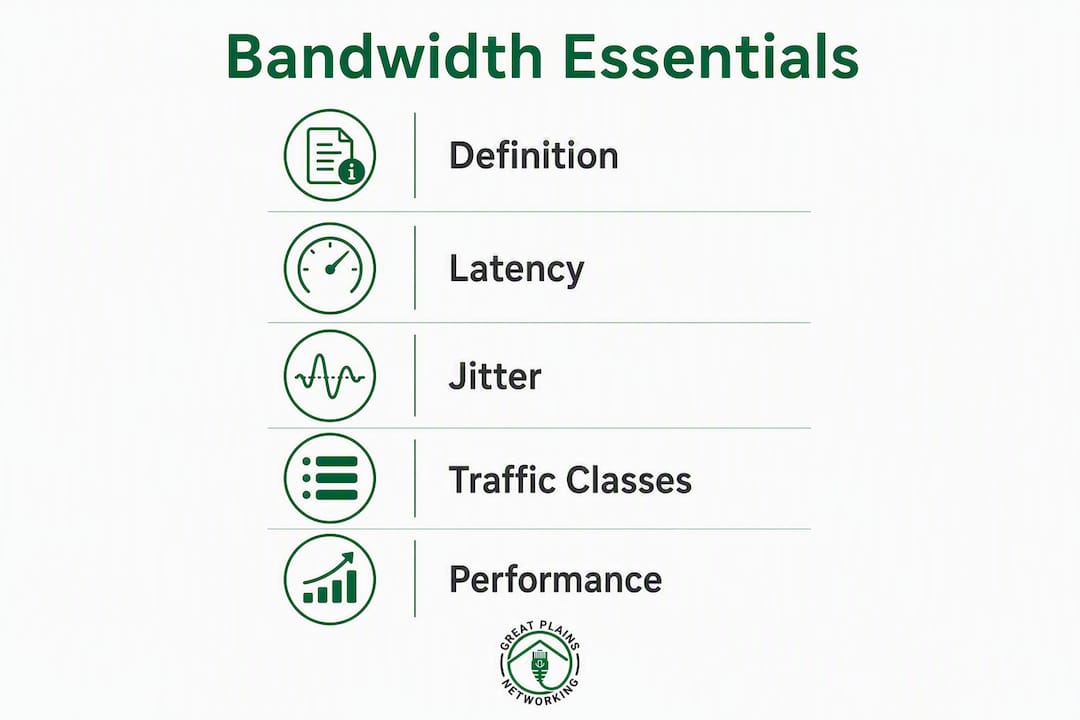
Latency and jitter are separate dimensions entirely. Latency is the one-way delay from sender to receiver; jitter is the variation in that delay from packet to packet. A PLC sending a 64-byte I/O update every millisecond does not need high bandwidth, but it needs very low and very consistent latency. A machine vision camera uploading a 4K inspection frame needs high bandwidth but can tolerate a few milliseconds of jitter. Conflating these terms leads to buying more bandwidth when the real problem is latency, or vice versa.
The IIC Networking Framework classifies industrial traffic by latency requirement rather than bandwidth alone, which is the correct framing for factory network design. Bandwidth and latency must both be planned, and they are not interchangeable.
How factory workloads map to bandwidth and latency requirements
| Workload | Typical bandwidth per node | Latency sensitivity | Jitter tolerance |
|---|---|---|---|
| PLC I/O (EtherNet/IP, PROFINET) | 1–10 Mbps | Extreme (sub-1 ms) | Very low |
| Machine vision (HD/4K inspection) | 100 Mbps–1 Gbps burst | Moderate | Moderate |
| Historian / data backup | 10–100 Mbps sustained | Low | High |
| Worker Wi-Fi / office apps | 5–50 Mbps per user | Low | High |
The units matter when choosing links. A 1 Gbps fiber uplink sounds large until four 4K cameras fire simultaneously during a production burst. ITU-T Y.4228 recommends supporting 1–10 Gbps or higher for video-based industrial services, which reflects how quickly vision deployments exhaust links that seemed adequate at design time.
Why does bandwidth directly affect manufacturing operations?
Bandwidth shortfalls in a factory do not just slow file transfers. They cause measurable production problems.
- Control loop instability. When a saturated uplink delays EtherNet/IP I/O packets, a motion controller can miss its update window and fault. A single dropped packet at the wrong moment can halt a line.
- Failed or delayed inspections. Machine vision systems that cannot push frames to the inference server fast enough either queue frames (introducing latency) or drop them. Either outcome means uninspected parts.
- Historian backup failures. Process historians write continuously. If the network path to the backup target is congested during peak production, write buffers fill and data is lost — a compliance and quality problem in regulated manufacturing.
- Remote support degradation. Technicians accessing HMIs or PLCs remotely over a saturated WAN link experience lag that makes fault diagnosis slow and error-prone.
- OT/IT convergence risks. As factories consolidate OT and IT onto shared infrastructure, bulk IT traffic (Windows updates, video conferencing, cloud backups) competes directly with control traffic unless segmentation and QoS are in place.
Unmanaged switches are a specific and common culprit. They cannot enforce VLANs or QoS, which means a broadcast storm from a misconfigured device reaches every port on the segment, including PLC ports. Replacing unmanaged switches with managed hardware is often the highest-impact first step in a factory network remediation. For a broader view of why reliable infrastructure matters to production continuity, see why manufacturers need reliable IT networks.
How do industrial traffic classes and latency targets guide your QoS design?
The IIC Networking Framework defines three latency classes that should drive every QoS policy you write:
- Extreme real-time (less than 1 ms): Motion control, safety systems, time-sensitive synchronization. These flows cannot share a queue with anything else.
- Real-time (1–100 ms): PLC I/O, SCADA polling, HMI updates. Needs priority queuing but tolerates brief contention.
- Non-real-time (greater than 100 ms): Historian writes, software updates, file transfers, worker Wi-Fi. Can be rate-limited and scheduled.
Traffic class mapping for QoS configuration
| Traffic type | Example protocols | Latency target | Recommended QoS action |
|---|---|---|---|
| Motion control / safety | PROFINET IRT, EtherNet/IP (motion) | < 1 ms | Strict priority queue; DSCP EF (46) |
| PLC I/O / SCADA | EtherNet/IP, Modbus TCP, PROFINET RT | 1–10 ms | High-priority queue; DSCP CS5 or EF |
| HMI / remote access | RDP, VNC over OT VLAN | 10–100 ms | Medium-priority queue; DSCP AF4 |
| Machine vision (burst) | UDP/TCP to inference server | 50–200 ms | Dedicated VLAN; rate-limited burst |
| Historian / backup | TCP bulk | > 100 ms | Best-effort or scheduled; DSCP CS1 |
| Worker Wi-Fi / office | HTTP/S, Teams, email | > 100 ms | Best-effort; policed at edge |
For a detailed walkthrough of DSCP marking and queue mapping in practice, the QoS guide for IT professionals covers configuration steps that apply directly to industrial switch deployments.
Pro Tip: When motion control or safety traffic is present, consider Time-Sensitive Networking (TSN) or IEEE 1588 Precision Time Protocol (PTP) for clock synchronization across the control network. These deterministic protocols eliminate jitter at the hardware level rather than relying on software QoS alone. For mobile assets where fiber is not feasible, Ultra Reliable Wireless Backhaul (URWB) can deliver 1 Gbps or higher Layer 2 connectivity with the low latency that control traffic requires.
How do you measure and monitor bandwidth on the factory floor?

Measurement before configuration is the rule. Without a verified baseline, you are guessing at QoS thresholds and uplink sizes.
Measurement plan
- Identify measurement points. Cover the WAN/last-mile uplink, every IDF-to-MDF uplink, camera switch uplinks, and edge switches feeding PLCs.
- Deploy flow collectors or SNMP polling at 30-second intervals or finer. Coarse 5-minute SNMP averages will miss burst events entirely.
- Enable SPAN or mirror ports on critical switches to feed a packet capture appliance for protocol-level inspection. Flow data tells you volume; packet capture tells you what protocol is consuming it.
- Record for at least two full production weeks, including shift changes, end-of-batch historian writes, and any scheduled maintenance windows that generate bulk traffic.
- Capture these metrics at each point: peak burst rate (Mbps), 95th-percentile sustained utilization, average utilization, packet loss rate, and round-trip jitter for control VLANs.
- Validate protocol distribution. Protocol-level visibility helps distinguish control traffic from bulk OT/IT data and can surface misconfigurations or unexpected flows before they cause production impact.
Monitoring topology
- Place out-of-band collectors (a dedicated management VLAN or separate management network) so monitoring traffic does not compete with production traffic.
- Use SNMP/streaming telemetry for continuous utilization trending and threshold alerting.
- Use flow collectors (NetFlow, sFlow, or IPFIX) for per-application and per-protocol breakdowns.
- Reserve packet capture for diagnostic deep dives, not continuous collection, to avoid storage and CPU overhead on production switches.
For ongoing operational monitoring practices tailored to manufacturing, the manufacturing network management best practices guide covers alert thresholds, runbook structure, and escalation paths.
How do you plan and size bandwidth for a factory network?
Sizing starts with the inventory and measurement data you collected, then applies headroom rules to arrive at link specifications and a phased deployment plan.
Sizing workflow
- Inventory all endpoints by type, average data rate, peak burst rate, PoE wattage, and latency class.
- Aggregate per-switch uplink demand. Sum the peak burst rates of all devices on a switch, then apply a concurrency factor based on your production data (not all devices burst simultaneously).
- Apply headroom rules. Design uplinks to remain at or below 70% sustained utilization; target 50% or less when mixing vision traffic with critical real-time control on the same uplink.
- Classify and separate traffic before finalizing uplink sizes. A well-segmented network with QoS often needs a smaller uplink than an unsegmented one because control traffic is protected from bulk flows.
- Pilot in one production cell before full deployment. Validate that QoS marks are honored end-to-end and that burst events stay within headroom.
- Stage the rollout by zone, validating each zone before proceeding.
Typical project timeline
| Phase | Activities | Typical duration (small/medium factory) |
|---|---|---|
| Assessment | Inventory, baseline measurement, traffic classification | 2–4 weeks |
| Design | Link sizing, QoS policy, topology design, PoE/electrical review | 1–2 weeks |
| Pilot | Deploy in one cell; validate QoS and headroom | 1–2 weeks |
| Staged deployment | Zone-by-zone rollout with validation checkpoints | 4–8 weeks |
| Validation | Full-production monitoring, alert tuning, documentation | 2 weeks |
Cost and link-speed factors
- Backbone link speeds: 1 Gbps fiber is the current floor for production networks; 2.5 Gbps and 10 Gbps are standard for IDF-to-MDF uplinks in vision-heavy environments; 25–100 Gbps applies to data center or large-plant MDF aggregation.
- Fiber vs. wireless backhaul: Single-mode fiber is preferred for long runs between buildings. Where trenching is cost-prohibitive, URWB provides 1 Gbps or higher Layer 2 connectivity as a viable alternative.
- PoE and electrical: Modern AI-driven vision cameras can require up to 90W PoE, which means switch power budgets and IDF electrical panels must be sized accordingly. A switch that runs out of PoE budget will drop ports, not just throttle them.
- SFP/optics: Budget for industrial-rated transceivers; consumer-grade optics fail in high-vibration or high-temperature environments.
For guidance on connecting OT devices to your business network during this process, see connecting industrial equipment to your business network.
How do you increase effective bandwidth without just buying bigger pipes?
Raw bandwidth upgrades are often the last resort, not the first. These strategies, applied in priority order, typically recover significant capacity before any new fiber is pulled.
- Segment with VLANs. Separate control, vision, historian, and office traffic onto dedicated VLANs. Broadcast domains shrink, and each class of traffic can be policed independently.
- Implement DSCP marking and priority queuing. Mark PLC and safety traffic with DSCP EF (46) and configure 4–8 priority queues on every managed switch. Port-based QoS with DSCP marking and ring topology between IDFs is the documented best practice for industrial Ethernet.
- Rate-limit non-critical traffic. Police historian bulk writes and Windows update traffic to a defined ceiling during production hours. Schedule large transfers to off-shift windows.
- Deploy edge compute for vision pre-processing. Running inference at the edge (on a local GPU server or edge appliance) means only results, not raw frames, travel the uplink. This can reduce vision-related uplink demand by an order of magnitude.
- Use 5 GHz and 6 GHz for wireless control and I/O. The 2.4 GHz band is not recommended for critical industrial control applications; reserve it for personnel access and non-critical apps only.
- Replace unmanaged switches on control paths. No QoS, no VLANs, no diagnostics — unmanaged switches are unsuitable for any path carrying PLC or safety traffic.
Additional configuration checklist:
- Enable storm control on all access ports to limit broadcast and multicast floods.
- Configure BPDU guard on access ports to prevent unauthorized switches from altering spanning tree.
- Use ring or hybrid topologies with fiber between IDFs for redundancy and deterministic failover.
- Plan PoE power budgets per switch before deployment; 90W devices require both switch hardware support and adequate electrical circuits at the IDF.
Pro Tip: Jumbo frames (approximately 9 KB MTU) can reduce CPU overhead and improve throughput for high-resolution vision traffic — but only when enabled end-to-end on every switch, server NIC, and storage target in the path. A single device in the path that does not support jumbo frames will silently fragment packets, which often causes more problems than the default 1,500-byte MTU. Validate end-to-end support before enabling jumbo frames in production.
For visibility as a security control alongside bandwidth management, the manufacturing data protection guide covers how segmentation and monitoring serve both operational and cybersecurity goals simultaneously.
Worked bandwidth calculation and deployment checklist
Inventory fields to collect per device
| Field | What to record |
|---|---|
| Device type | Camera, PLC, HMI, historian server, AP |
| Average data rate | Mbps sustained during production |
| Peak burst rate | Mbps at maximum inspection or I/O cycle |
| Burst duration | Seconds per burst event |
| PoE wattage | Watts required (0, 30, 60, or 90W) |
| Latency class | Extreme real-time, real-time, or non-real-time |
| VLAN assignment | Control, vision, historian, office |
Worked example: production line with machine vision
Scenario: One IDF switch serves 8 machine vision cameras, 4 PLCs, and 2 HMIs.
Camera uplink demand:
- Each camera: 200 Mbps peak burst, 40 Mbps average sustained
- 8 cameras simultaneous burst: 8 × 200 Mbps = 1,600 Mbps peak
- Apply 60% concurrency factor (not all cameras fire at once): 1,600 × 0.60 = 960 Mbps vision peak
Control traffic:
- 4 PLCs at 5 Mbps each: 20 Mbps
- 2 HMIs at 10 Mbps each: 20 Mbps
- Control subtotal: 40 Mbps
Total IDF uplink demand at peak: 960 + 40 = 1,000 Mbps
Apply headroom rule: With mixed vision and critical control, target 50% utilization ceiling. Required uplink capacity: 1,000 Mbps ÷ 0.50 = 2,000 Mbps minimum.
Recommendation: A 10 Gbps uplink from this IDF to the MDF, which keeps peak demand at roughly 20% of link capacity and leaves room for historian writes and growth. A 1 Gbps uplink would be saturated; a 2.5 Gbps uplink would be heavily utilized during burst events, above the recommended sustained utilization ceiling.
Alert threshold and deployment QA checklist
- Set utilization alerts at 70% sustained on all uplinks (50% on mixed vision/control uplinks).
- Verify DSCP marks are preserved end-to-end by capturing traffic at the MDF and confirming EF-marked packets from PLCs arrive with markings intact.
- Confirm PoE power budget is not exceeded on any switch before powering all cameras simultaneously.
- Validate jumbo frame support end-to-end before enabling on vision VLANs.
- Run a 72-hour production soak after each zone deployment before proceeding to the next.
- Document baseline metrics post-deployment for future capacity planning comparisons.
Key Takeaways
Factory network bandwidth planning requires measurement-based sizing, traffic segmentation, and QoS enforcement — not consumer rules of thumb or raw pipe upgrades alone.
| Point | Details |
|---|---|
| Measure peak bursts, not averages | Capture 95th-percentile and burst rates at every IDF uplink over two full production weeks. |
| Apply the 70%/50% headroom rule | Keep uplinks at or below 70% sustained utilization; target 50% when mixing vision with critical control traffic. |
| Classify and protect control traffic | Mark PLC and safety flows with DSCP EF and place them in strict-priority queues before any other optimization. |
| Size uplinks from measured data | A production line with 8 cameras and 4 PLCs can require a 10 Gbps IDF uplink once headroom rules are applied. |
| Greatplainsnetworking provides managed assessments | For factories in Norman, Moore, and Oklahoma City, Greatplainsnetworking delivers bandwidth assessments, QoS configuration, and 24/7 monitoring as a managed service. |
The bandwidth problem most factories are solving too late
There is a pattern that shows up repeatedly in factory network assessments: the network was designed for the equipment that existed at commissioning, not for what the floor looks like three years later. A line that started with two cameras now has eight. The historian that once wrote 10 MB per batch now writes 10 GB. The WAN link that handled remote support for one technician now carries four simultaneous sessions plus cloud backup.
The conventional advice is to buy more bandwidth. That is often the wrong first move. Segmentation and QoS can recover a surprising amount of effective capacity from a congested network, and they cost far less than a fiber upgrade or a new WAN circuit. The factories that get into trouble are the ones that skip the measurement step and go straight to hardware procurement, then find that the new 10 Gbps uplink is still saturated because broadcast storms from unmanaged switches are consuming it.
What actually works is the sequence: measure first, classify second, protect control traffic third, then size the uplinks to match what the data shows. The headroom rules (70% sustained, 50% for mixed vision and control) exist because bursty vision traffic will always find a way to fill whatever pipe you give it if you do not constrain it with QoS and rate limiting.
The other underestimated factor is PoE and electrical planning. Network teams often spec the switch hardware correctly but forget that 90W PoE cameras require both switch power budget and adequate circuit capacity at the IDF. A switch that runs out of PoE budget mid-deployment does not warn you gracefully — it drops ports.
How Greatplainsnetworking supports factory network assessments in Oklahoma
Factory IT managers in Norman, Moore, and Oklahoma City have a specific challenge: they need OT-aware network expertise without the overhead of a large enterprise IT department. Greatplainsnetworking delivers exactly that through a structured engagement model built around the assessment-first approach this guide describes.

The engagement starts with a documented bandwidth and traffic assessment: baseline measurement at every IDF uplink, protocol-level traffic classification, PoE audit, and a written sizing recommendation. From there, Greatplainsnetworking configures QoS policies, VLAN segmentation, and alert thresholds in a pilot cell before any production-wide changes are made. Ongoing managed IT support includes 24/7 monitoring with utilization alerts, same-day response for network faults, and periodic capacity reviews as your production environment grows.
No long-term contracts are required. If your factory floor is running on unmanaged switches, aging uplinks, or a network that was never designed for machine vision, contact Greatplainsnetworking to schedule a factory network assessment.
Useful sources for factory network planning
These references support the standards, protocols, and design guidance throughout this article.
-
ITU-T Y.4228 — IIoT Infrastructure Requirements for Smart Manufacturing: The ITU's formal requirements framework for industrial IoT infrastructure, including bandwidth and latency targets for video-based and real-time industrial services. Supports the fundamentals and planning sections.
-
IIC Industrial Internet Networking Framework: Defines latency classes (extreme real-time, real-time, non-real-time) and QoS requirements for industrial networks. Directly supports the traffic classification and QoS sections.
-
NIST AMS 300-8r1 — Wireless User Requirements for the Factory Workcell: NIST's detailed requirements for wireless communications in factory environments, covering reliability, latency, and the radio-frequency challenges of metallic manufacturing spaces. Supports wireless guidance throughout.
-
Cisco Industrial Automation Wireless Design Guide: Covers spectrum selection (5 GHz and 6 GHz for critical I/O), URWB as a fiber alternative, and wireless design for industrial control applications. Supports the optimization and planning sections.
-
Cisco Modern Networks: AI-Ready Manufacturing: Addresses PoE power planning (up to 90W), uplink sizing for AI-driven vision (2.5 Gbps, 10 Gbps), and electrical design considerations. Supports the sizing, PoE, and checklist sections.
-
Cisco Live BRKIOT-2746 — Industrial Network Design: Source for the 70%/50% headroom rules, burst-aware uplink design, and jumbo frame guidance for vision traffic. Supports the sizing, checklist, and worked example sections.
-
Industrial Monitor Direct — Industrial Ethernet Network Design: Practical design guidance covering managed switch requirements, VLAN/QoS configuration, DSCP marking, ring topologies, and the risks of unmanaged switches on control paths. Supports the fundamentals, optimization, and why-it-matters sections.
-
Dell Technologies Validated Design for Manufacturing Edge: Covers protocol-level visibility as both an operational and cybersecurity control, and baseline monitoring requirements for manufacturing edge deployments. Supports the monitoring and security sections.
-
5G-ACIA — 5G Traffic Model for Industrial Use Cases: Analyzes actual data volumes and traffic types for industrial automation use cases, providing a realistic traffic model for network load prediction. Supports the traffic characterization and planning sections.
Recommended
Want help putting this into practice?
We'll audit your security, speed, and hardware in under an hour — no commitment, no sales pitch. Just a clear roadmap of what to fix and why.